Parallax Propeller Book - RC Decay Circuit
Prerequisites:
- Completed Set-Up (Chapter 0)
- Understand Propeller Basics (Chapter 1)
- Understand Propeller Definitions and Terms (Chapter 2)
Equipment:
- Computer with Win 10 and the Set Up files already Installed
-
Propeller Activity Board (PAB)
or Propeller FLiP Microcontroller Module (FLiP) -
USB Cable to connect PAB to Computer (USB to USB mini-B)
or to FliP (USB to USB micro-B connector) - Propeller Tool installed on Computer
Objective:
- Learn about RC decay circuit
- Learn how to measure variable Resistance
Components:
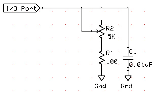
- Resistor (R1) – 100 Ω (brown-black-brown)
- Potentiometer (R2) – 5 KΩ (slide or rotary linear), can be any value up to 15 KΩ
- Capacitor (C1) 0.01μF - 10nF
Basic RC decay circuit
RC decay measurements are typically performed by charging a capacitor (C) and then monitoring the time it takes the capacitor to discharge through a resistor (R).
In most RC decay circuits, one of the values is fixed, and the other varies with an environmental variable.
For example, the circuit in Figure 5-1 is used to measure a potentiometer knob’s position.
The value of C is fixed at 0.01 μF, and the value of R varies with the position of the potentiometer’s adjusting knob (the environmental variable).
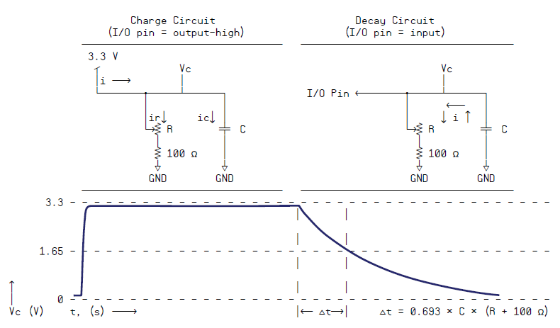
Measuring RC Decay
Before taking the RC decay time measurement, the Propeller chip needs to set the I/O pin connected to the circuit to output-high.
This charges the capacitor up to 3.3 V as shown on the left side of Figure 5-2.
Then, the Propeller chip starts the RC decay measurement by setting the I/O pin to input, as shown on the right side of Figure 5-2.
When the I/O pin changes to input, the charge built up in the capacitor drains through the variable resistor.
The time it takes the capacitor to discharge from 3.3 V down to the I/O pin’s 1.65 V threshold is:
Δt = 0.693 × C × (R + 100 Ω)
Since 0.693, C and 100 Ω are all constants, the time Δt it takes for the circuit to decay is directly proportional to R, the variable resistor’s resistance.
Why is there a 100 Ω resistor below the potentiometer?
One end of the potentiometer’s range of motion sets the resistance R to 5 kΩ, and the other end sets it to 0 Ω.
Take a look at the left side of Figure 5-2, and think about what would happen if the potentiometer gets adjusted to 0 Ω with no 100 Ω resistor.
The I/O pin that’s trying to supply 3.3 V to the circuit would get shorted to Ground.
Although a Propeller I/O pin can survive this, it causes fluctuations in the supply voltage that could affect the performance of other circuits in a larger application.
A 100 Ω series resistor can instead be placed between the I/O pin and the RC circuit.
The main benefit of this approach is that it reduces any potential effects of even a brief current inrush when the I/O pin starts charging the capacitor.
The main drawback is that a protection resistor at the I/O pin forms a voltage divider with the potentiometer’s resistance, which in turn prevents the capacitor from charging to 3.3 V.
Instead, the capacitor charges to 3.3 V × R ÷ (R + 100). As the value of R gets smaller, the voltage the capacitor can charge to before the decay measurement starts also drops.
Although Δt would still vary with R over most of the potentiometer’s range of motion, the measured decay time would no longer be directly proportional to resistance like it is with the circuit in Figure 5-2.
“Counting” the RC Decay Measurement
Before the RC decay measurement, the capacitor must be charged.
Here is a piece of code that sets P7 to output-high, then waits for 10 μs, which is more than ample for charging the 0.01 μF capacitor in the Figure 5-1 RC network.
        dira[7] := outa[7] := 1
       waitcnt(clkfreq/100_000 + cnt)
To start the decay measurement, clear the PHS register, and then set the I/O pin that’s charging the capacitor to input:
	phsa~
	dira[7]~
After clearing phsa and dira, the program is free to perform other tasks during the measurement.
At some later time, the program can come back and copy the phsa register contents to a variable.
Of course, the program should make sure to wait long enough for the decay measurement to complete.
This can be done by polling the clock, waiting for the decay pin to go low, or performing a task that is known to take longer than the decay measurement.
To complete the measurement, copy the phsa register to another variable and subtract 624 from it to account for the number of clock ticks between phsa~ and dira[7]~.
The result of this subtraction can also be set to a minimum of 0 with #> 0.
This will make more sense than -624 when the resistance is so low that it pulls the I/O pin’s output-high signal low.
time := (phsa – 624) #> 0
Where did 624 come from?
The number of clock ticks between phsa~ and dira[7]~ was determined by replacing the 0.01 μF capacitor with a 100 pF capacitor and finding the lowest value before zero was returned.
In the test program, time := phsa replaces time := (phsa – 624) #> 0, and the lowest measurable value was 625.
The TestRcDecay.spin object applies the techniques just discussed to measure RC decay in a circuit with variable resistance controlled by the position of a potentiometer’s adjusting knob.
The program displays a “working on other tasks” message after starting the RC decay measurement to demonstrate that the counter module automatically increments the phsa register until the voltage applied to P7 decays below the Propeller chip’s 1.65 V I/O pin threshold.
The program can then check back at a later time to find out the value stored in phsa.
Running the Application:
- Build the circuit in Figure 5-1 and connect to P7 on the Propeller chip.
- Open the TestRcDecay.spin object. It will call methods in Parallax Serial Terminal.spin, so make sure they are both saved in the same folder.
- Open Parallax Serial Terminal and set its Com Port field to the same port the
Propeller Tool software uses to load programs into the Propeller chip.
Press [F7] Function Key to get the Com Port Number. - Use the Propeller Tool to load TestRcDecay.spin into the Propeller chip.
- Immediately click the Parallax Serial Terminal’s Enable button.
(Don’t wait for the program to finish loading. In fact, you can click the Parallax Serial Terminal’s Enable button immediately after you have pressed [F10] or [F11] Function Key in the Propeller Tool software.) - Try adjusting the potentiometer knob to various positions and note the time values. They
should vary in proportion to the potentiometer knob’s position.
Low value for low resistance and High value for high resistance.
'' http://www.mirox.us/Parallax/Propeller/Book/Book-Ch5/TestRcDecay.spin
'' Test RC circuit decay measurements on P7.

CON
  _clkmode = xtal1 + pll16x                  ' System clock → 80 MHz
  _xinfreq = 5_000_000

OBJ
  pst : "Parallax Serial Terminal"           ' Use with Parallax Serial Terminal to
                                             ' display values
PUB Init
  'Start Parallax Serial Terminal; waits 1 s for you to click Enable button
  pst.Start(115_200)			 ' Configure counter module.
  ctra[30..26] := %01000                 ' Set mode to "POS detector"
  ctra[5..0] := 7                        ' Set APIN to 7 (P7)
  frqa := 1                              ' Increment phsa by 1 for each clock tick
  main                                   ' Call the Main method

PUB Main | time
'' Repeatedly takes and displays P7 RC decay measurements.

  repeat
     ' Charge RC circuit.
     dira[7] := outa[7] := 1               ' Set pin to output-high
     waitcnt(clkfreq/100_000 + cnt)        ' Wait for circuit to charge

     ' Start RC decay measurement.  It's automatic after this...
     phsa~                                  ' Clear the phsa register
     dira[7]~                               ' Pin to input stops charging circuit

     ' Optional - do other things during the measurement.

     pst.Str(String(pst#NL, pst#NL, "Working on other tasks", pst#NL))
     repeat 22
       pst.Char(".")
       waitcnt(clkfreq/20 + cnt)

' Measurement has been ready for a while.  Adjust ticks between phsa~ and dira[17]~.

     time := (phsa - 624) #> 0

     ' Display Result
     pst.Str(String(pst#NL, "time = "))
     pst.Dec(time)
     waitcnt(clkfreq/2 + cnt)
RC Decay Data
| Potentiometer Resistance Nominal |
Potentiometer Resistance Actual |
Returned Time Value |
Corrected Value |
Ratio | Displayed Resistance |
Position |
|---|---|---|---|---|---|---|
| 100 Ohm | 0 Ohm | 83 | 0 | 0 Ohm | 0 % | |
| 1,250 Ohm | 1090 Ohm | 769 | 686 | 1.59 | 1054 Ohm | 25% |
| 2,500 Ohm | 2380 Ohm | 1683 | 1600 | 1.48 | 2331 Ohm | 50% |
| 3,750 Ohm | 3780 Ohm | 2604 | 2521 | 1.50 | 3606 Ohm | 75% |
| 5,000 Ohm | 4680 Ohm | 3188 | 3105 | 1.51 | 4653 Ohm | 100% |
| Infinity | 88270818 | N/A |
It looks like the Potentiometer resolution over the slider range is linear, as the Ratio between the Actual resistance and the corrected Value is about 1.5 over the entire range.
Therefore if we multiply the returned value by 1.5 after we have subtracted the minimum value (83) which represents the 100 Ohm resistor’s contribution, then we get the actual resistance.
However, we can not multiply by 1.5 directly, we have to first multiply by 15 and then divide by 10 to get the correct Resistance value.
That is achieved by this code:
	Rohm := (time-83)*1_5
     	Rohm := Rohm/10
The new corrected Application is:
http://www.mirox.us/Parallax/Propeller/Book/Book-Ch5/TestRcDecayRohm.spin.
Another version of the Application is:
http://www.mirox.us/Parallax/Propeller/Book/Book-Ch5/TestRcDecayRohmA.spin.
Links to related Webpages
Click the link in the list below to navigate to a detailed webpage about the listed subject.
- PREVIOUS: Parallax Propeller Book - Chapter 4 Part 3 (Programming)
- NEXT: Parallax Propeller Book - Chapter 6 (Servo Controlling)